I- Power Dissipated in the Cavity
I.1- Main parameters
Incident Power : Prf = 40 MW
Pulse length : t = 4.5 to 6 microseconds
Repetition Frequency : fr=5 to 25 Hz
Quality Factor : Q = 180000
Resonant Frequency : F = 2998.550 MHz
Stored Energy is given by
![]()
Dissipated Power is given by :
![]()
With
![]()
![]()
![]()
![]()
I.2- Transient Power
For t = 6 microseconds, the stored energy is 148 Joules and the instantaneous dissipated power is 15.5 MW.
I.3- Average Power
For t = 6 microseconds and fr = 25 Hz, the average dissipated power is 1750 W.
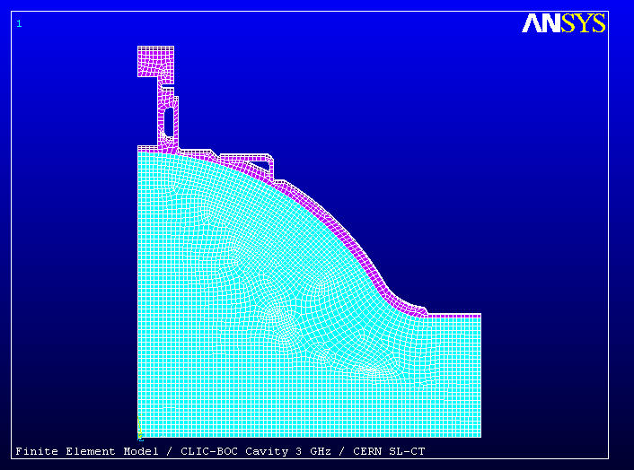
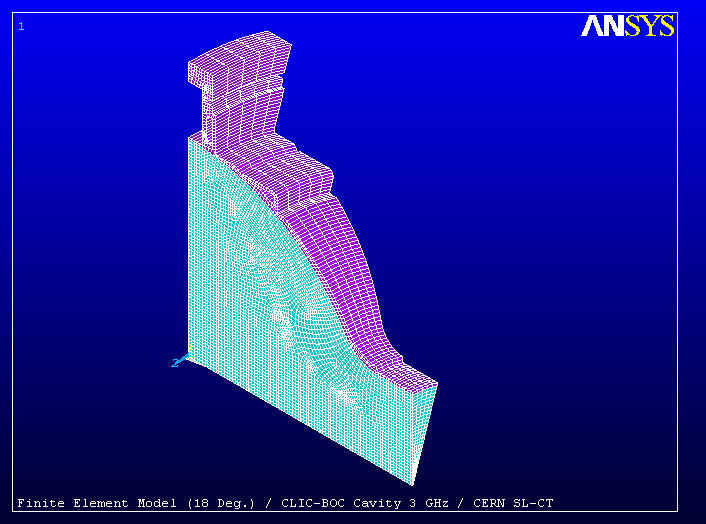
II- HF FINITE ELEMENT ANALYSIS
II.1- Finite Element Model
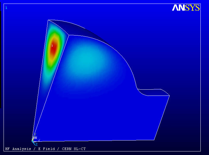
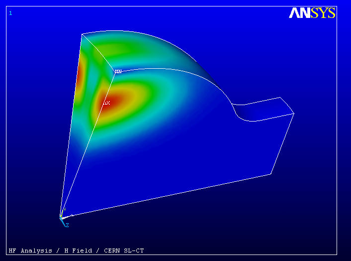
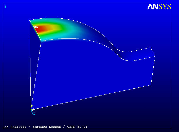
II.2- RF Analysis
Scaling @ 1750 Watts Total dissipated power
Peak Electric Field : 8.6 MV/m
Peak Magnetic Field : 22.8 KA/m
III- COOLING DESIGN
III.1- Coolant Debit : Qc
Medium : Water 303 K
Power to be dissipated : 1750 Watts
Temperature rise of the coolant : 1 K
Qc = 1.5 m3/h (1 m3/h for the waveguide cooling channels
and 0.5 m3/h for the cells cooling channels)
III.2- Prototype Cavity Design
2 cooling channels on each side of the waveguide, section 100 mm2

III.3- Main Cooling Parameters
Cavity Material : OFE Copper (k=400 W/m/K, Specific Heat= 385 J/Kg/K)
Coolant Velocity : 1.3 m/s
Reynolds Number : 18000
Global Exchange coefficient : 4700 W/m2/K for the waveguide cooling
channels and 7800 W/m2/K for the cells cooling channels
Total Pressure Drop : 0.2 Bar
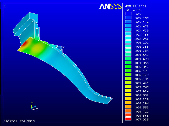
IV- COUPLED FIELD FINITE ELEMENT ANALYSIS
The cavity has been sequentially studied in the RF, thermal and mechanical domain. Results from one domain are inputs for the subsequent domain. Thus it's possible to track, from the initial RF analysis, the temperature evolution, cavity deformations and frequency shift.
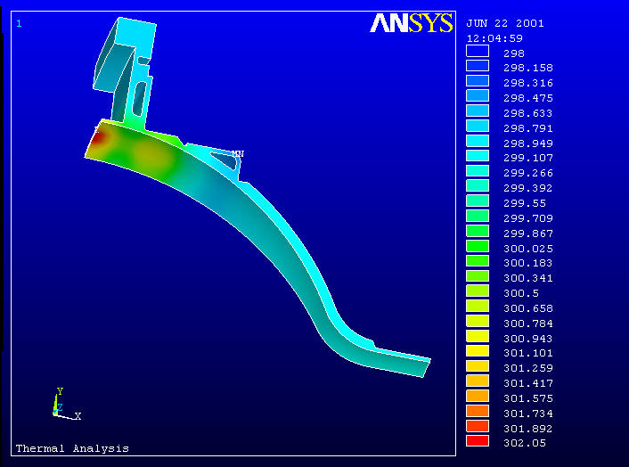
For the thermal analysis, water convection coefficients of 4700 and 7800 W/m2/K at 303 K have been applied in the cooling channels and air convection coefficient of 10 W/m2/K at 303 K on all other external surfaces.
For the mechanical analysis, atmospheric pressure has been applied on all external surfaces and on the cut-offs.
Results are presented for "pulsed mode" and "step equivalent mode".
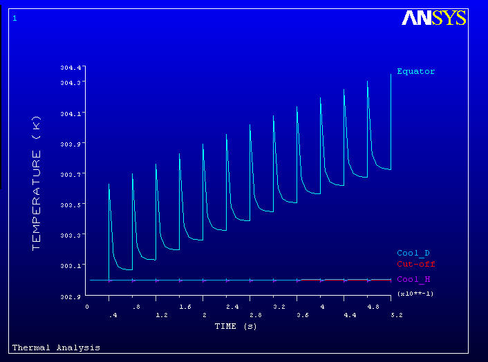
IV.1- Pulsed Mode
The cavity has been studied over a period of 0.52 seconds, corresponding to 12 pulses (25 Hz). The pulse is of triangular shape with maximum energy 148 Joules at 6 çs.
The maximum temperature, located at the equator, is +303.7 K. The temperature rise caused by one RF pulse is 0.65 K.
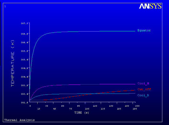
IV.2- Equivalent Step mode
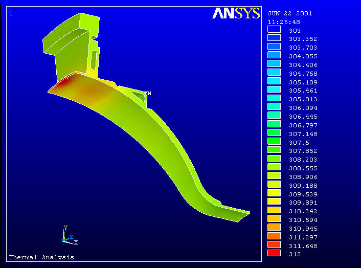
The equivalent step is the one corresponding to the mean dissipated power (1750 Watts). The cavity has been studied over a period of 200 seconds (steady state reached). The maximum temperature is 307.02 K (+4.02 K).
V- FREQUENCY SHIFT DUE TO ATMOSPHERIC PRESSURE
In that case only the atmospheric pressure has been applied on all the external surfaces of the cavity and on the cut-offs (no power dissipated inducing a temperature rise). The frequency shift is + 8 KHz.
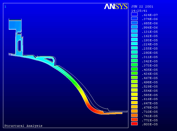
The maximum total displacement is 8 microns.
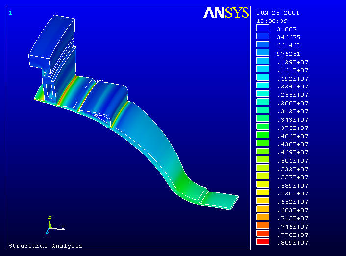
The maximum Von Mises equivalent stress is 8 MPa.
VI- FREQUENCY SHIFT WITH COOLING WATER TEMPERATURE
The cooling water temperature should vary between 298 K and 308 K in order to tune the cavity of Ý 250 KHz.
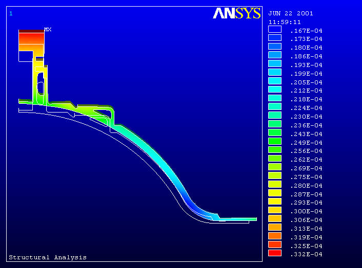
VI.1- Cooling Water 303 K (Nominal value)
The frequency shift is -110 KHz
The maximum temperature offset is + 4.02K
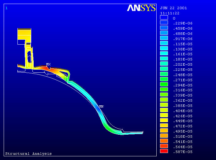
The maximum total displacement is 6 microns.
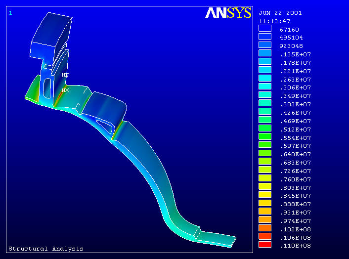
The maximum Von Mises equivalent stress is 11 MPa.
VI.2- Cooling Water 308 K (+5K)
The frequency shift is -210 KHz
The maximum temperature offset is + 4K.
The maximum total displacement is 33 microns.
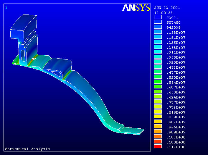
The maximum Von Mises equivalent stress is 11 MPa.
VI.3- Cooling Water 298 K (-5K)
The frequency shift is +210 KHz
The maximum temperature offset is + 4.05K.
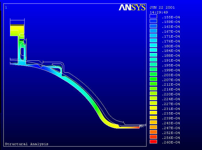
The maximum total displacement is 26 microns.
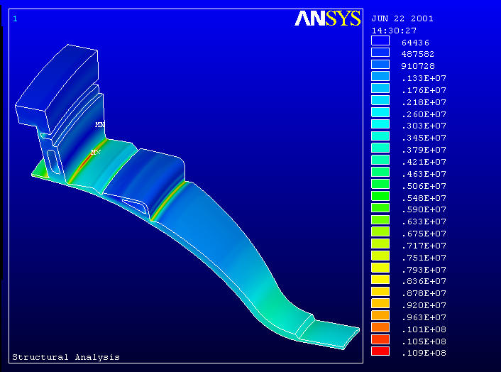
The maximum Von Mises equivalent stress is 11 MPa.